Driven RLC circuit
Description
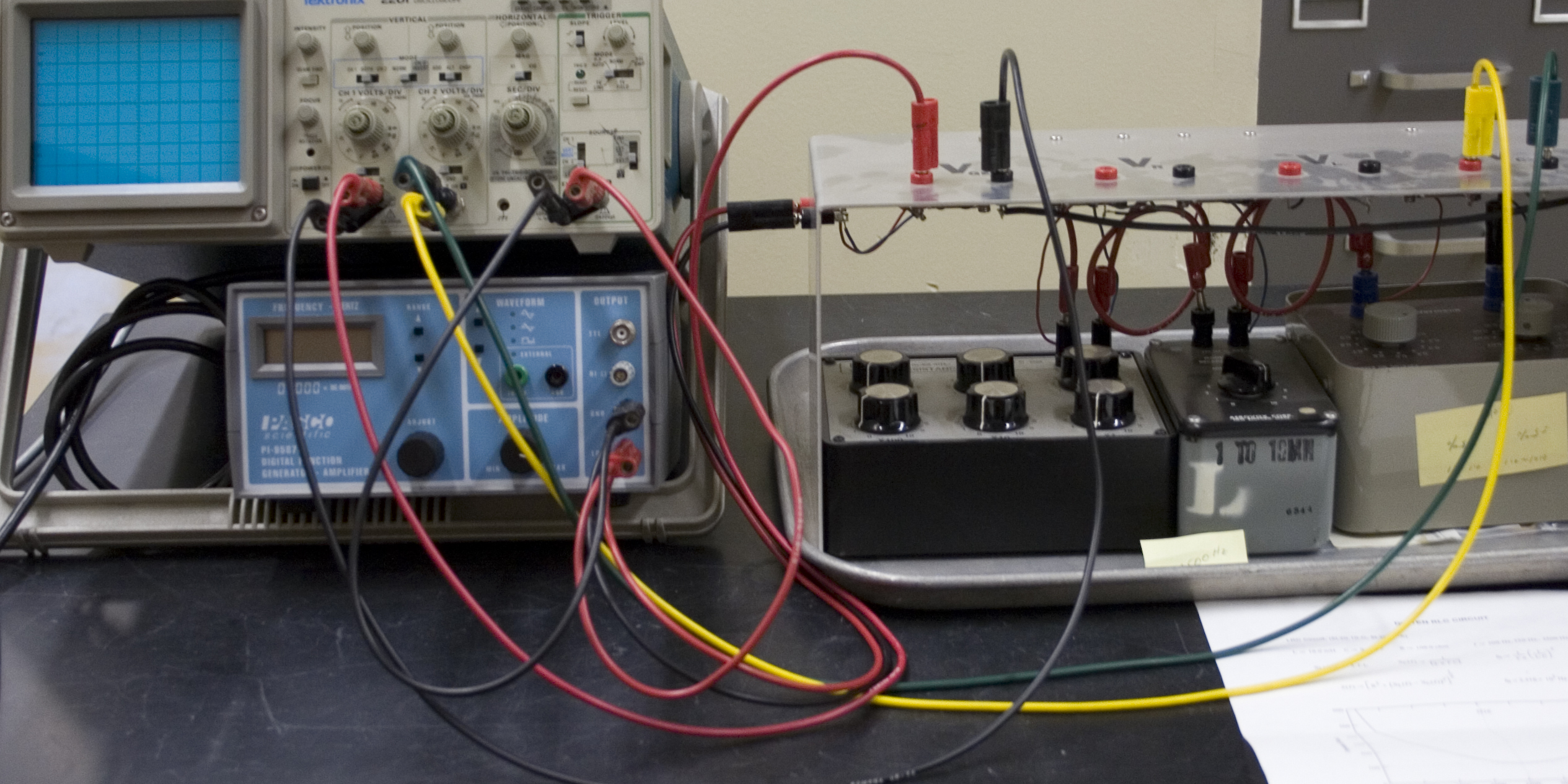
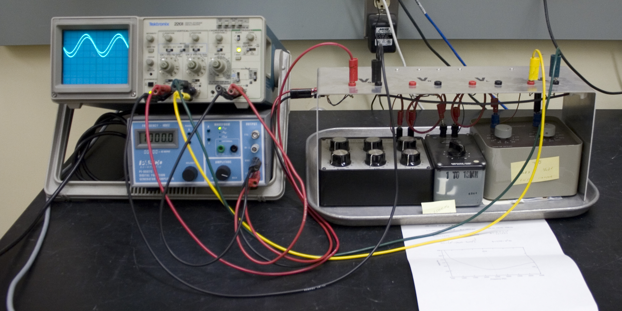
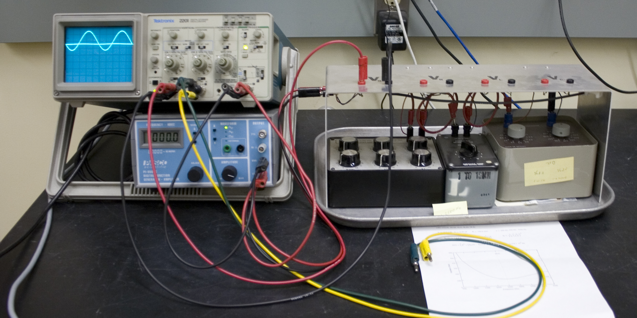
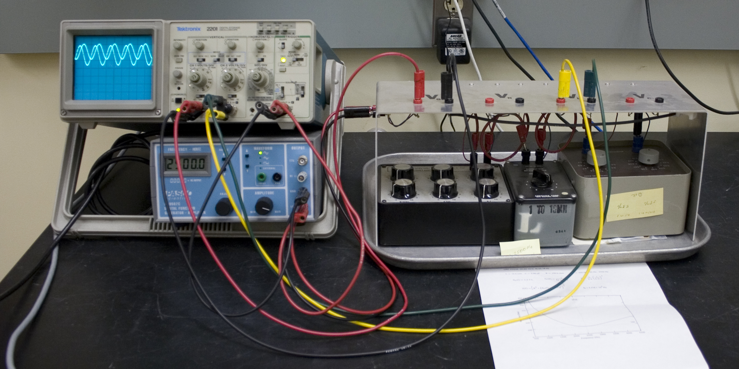
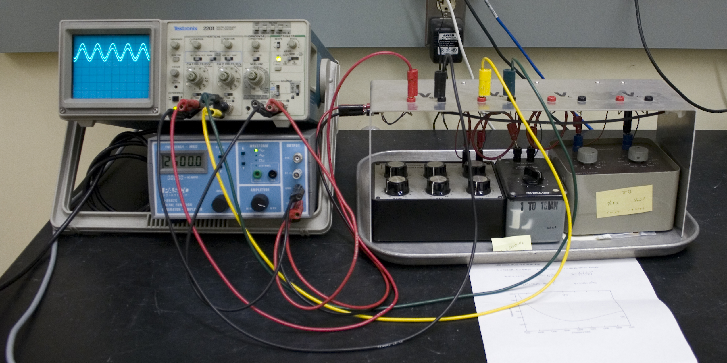
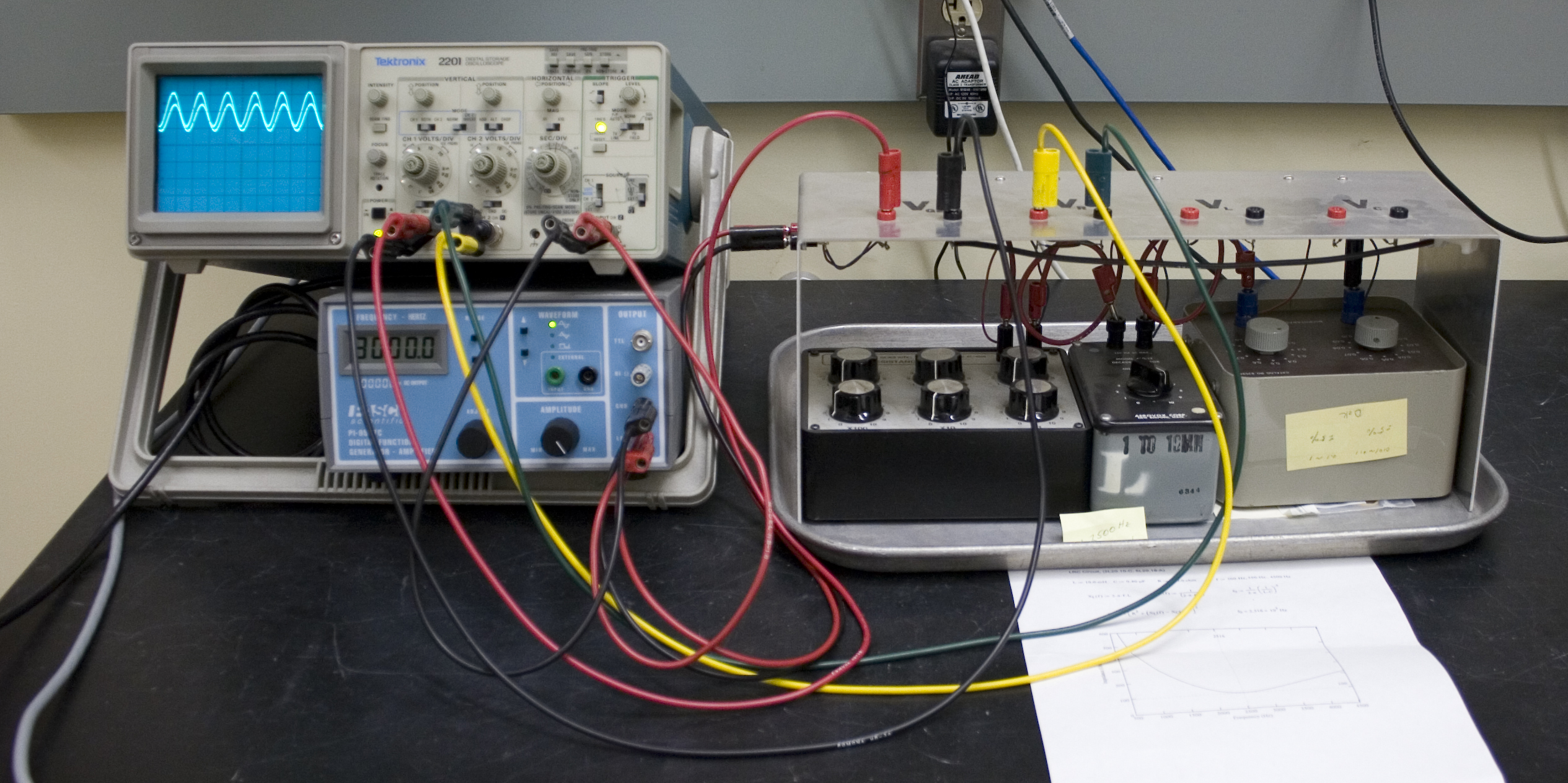
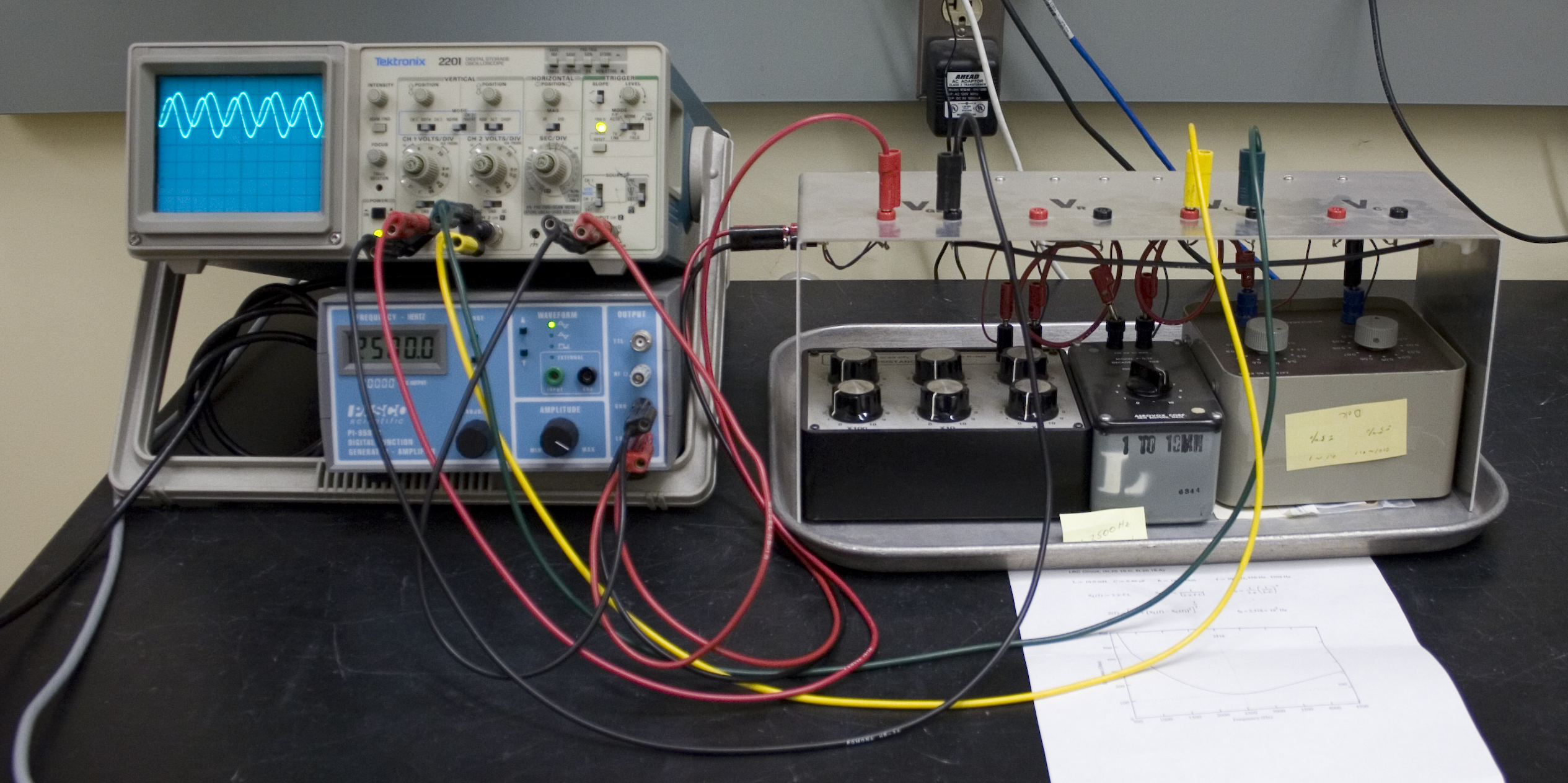
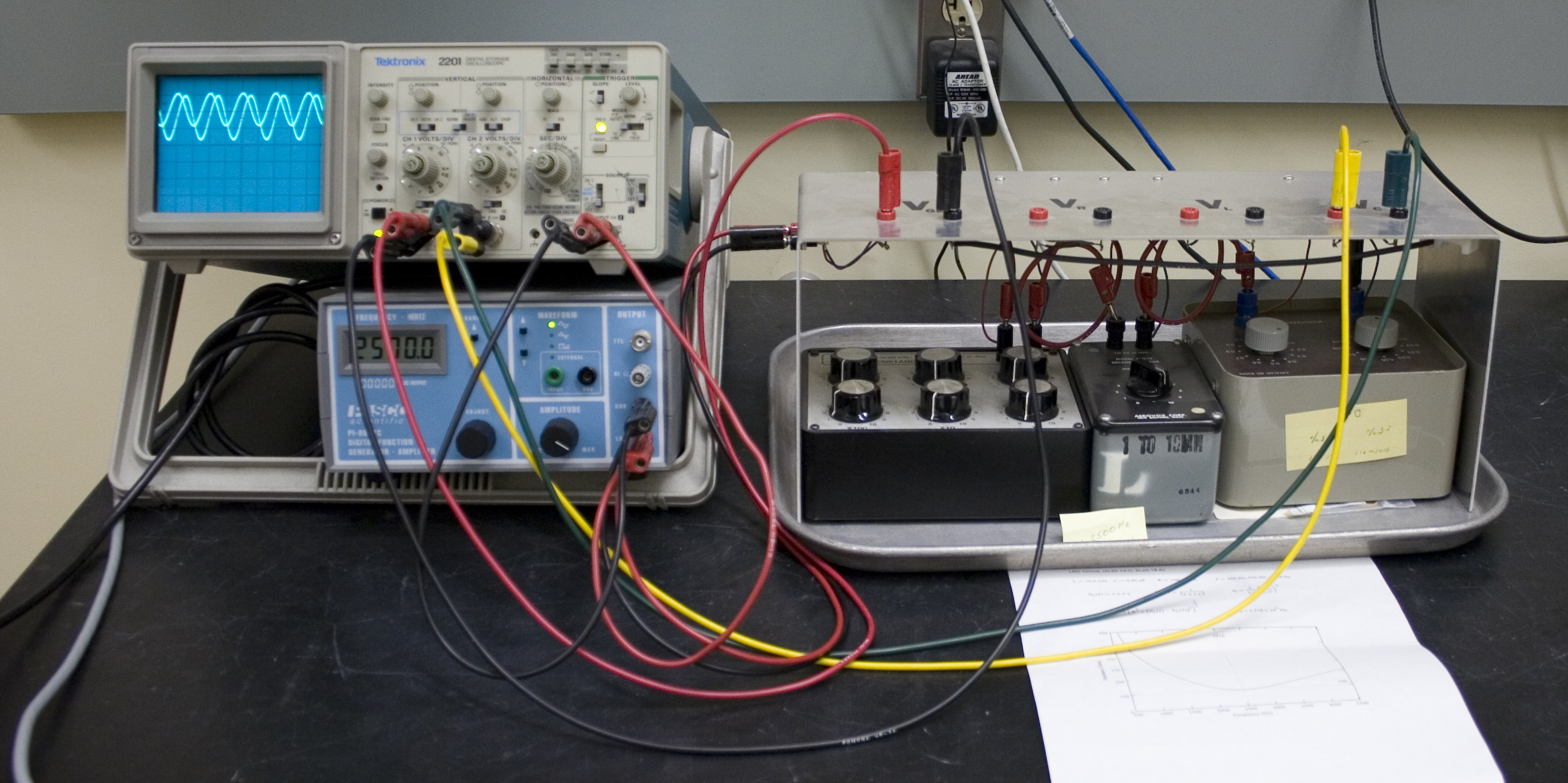
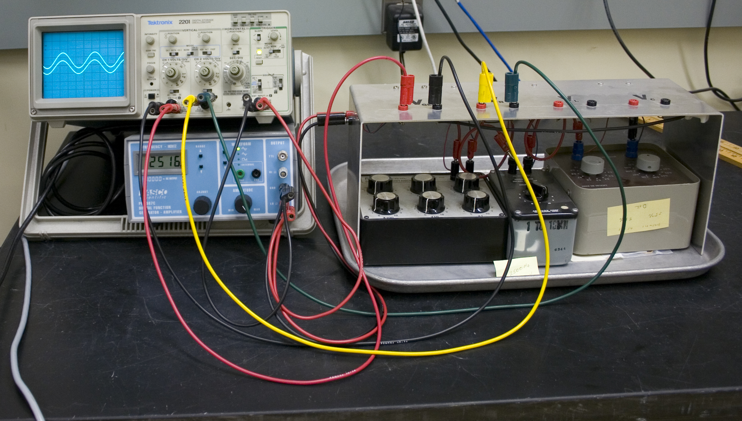
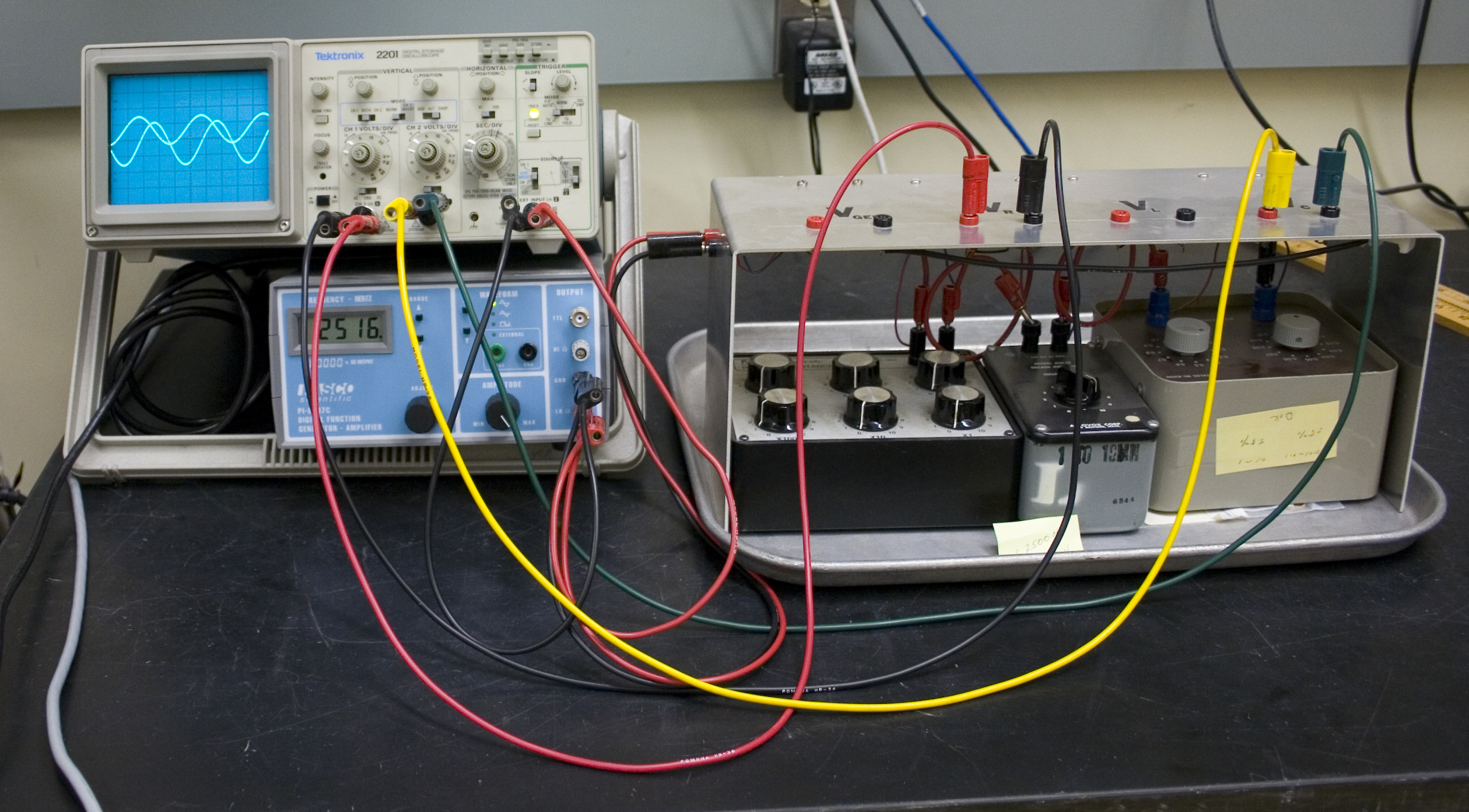
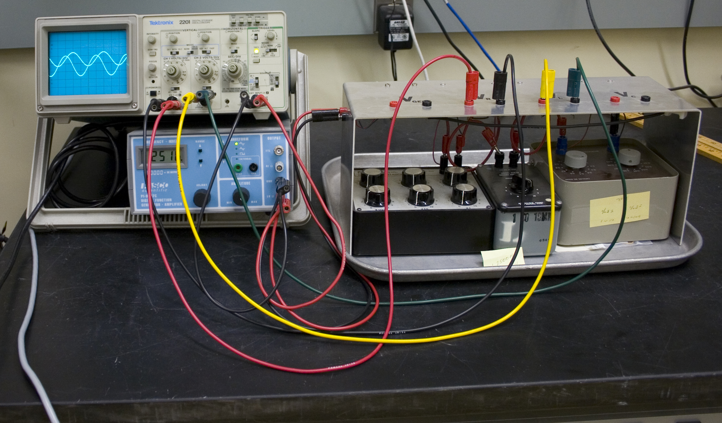
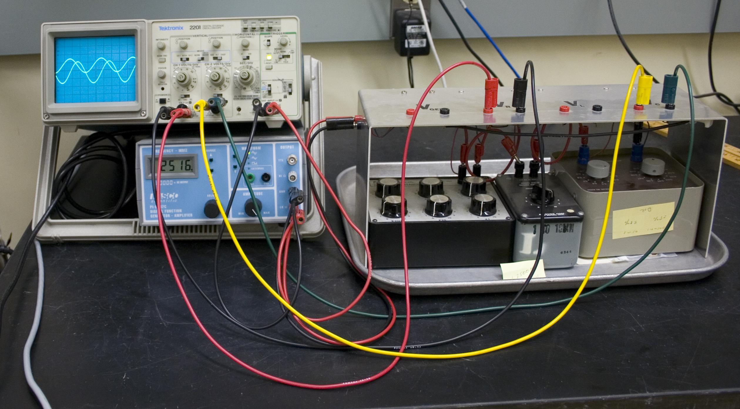
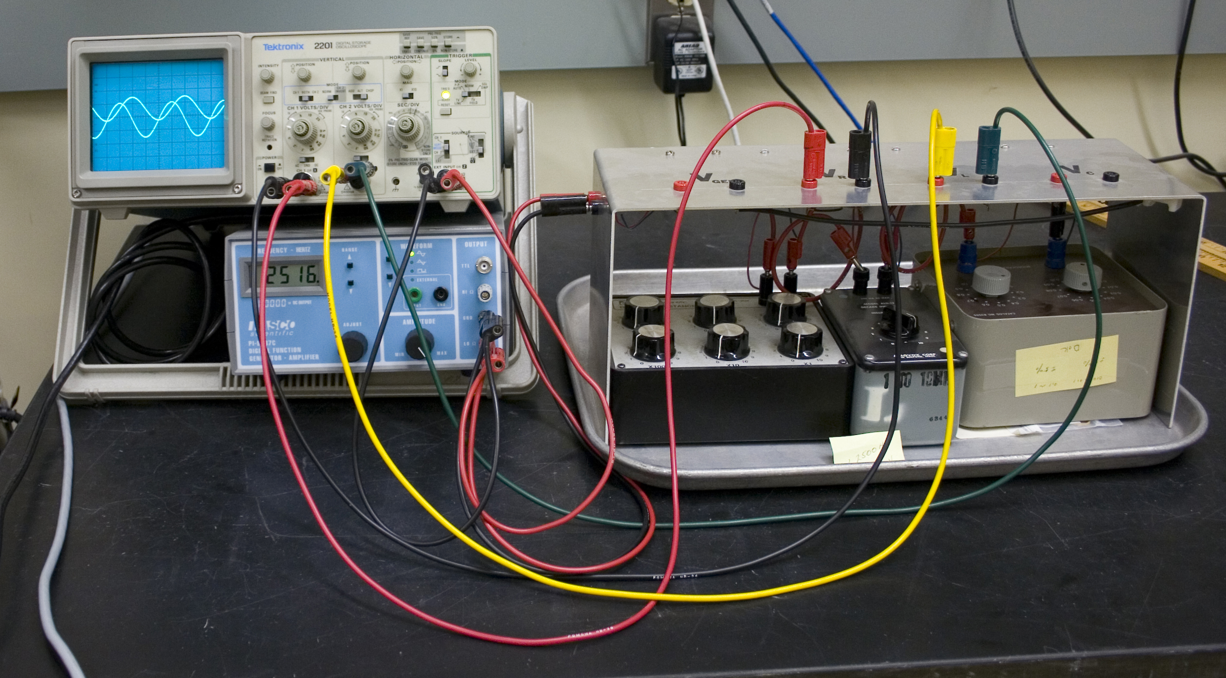
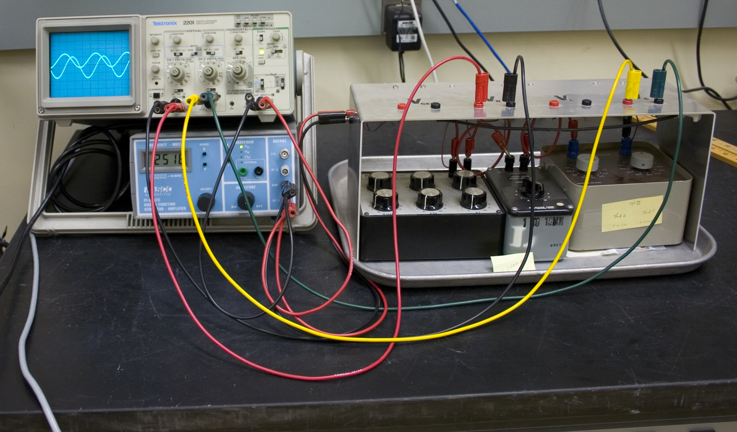
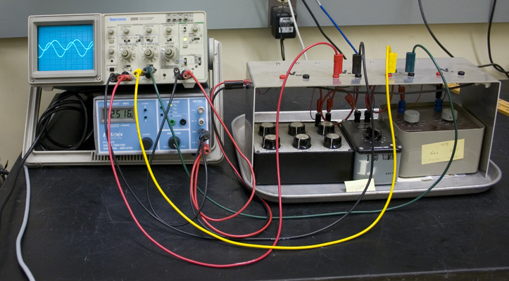
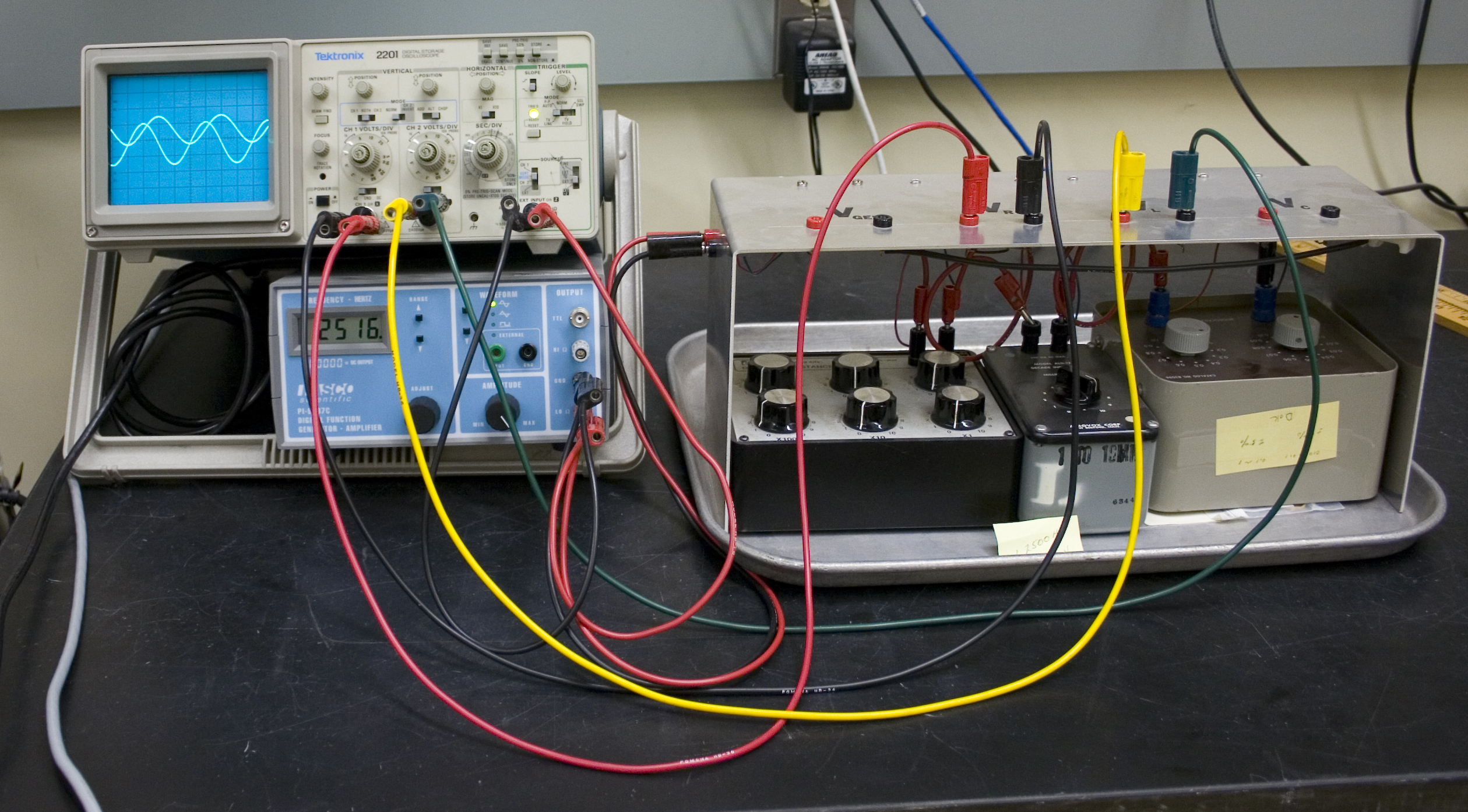
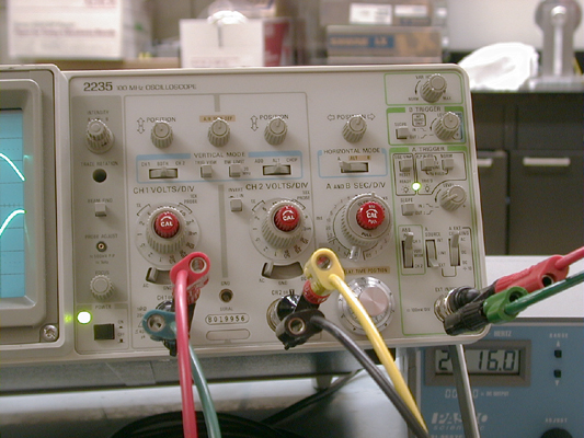
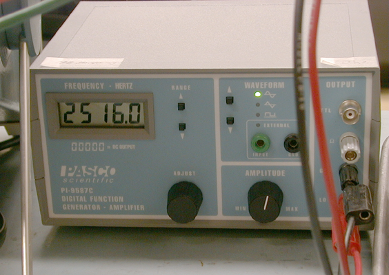
A driven RLC circuit is connected to an oscilloscope to display the voltage and current across the resistor, inductor, and capacitor individually as the circuit is driven by an AC supply. By analyzing the waveforms, the phase relationships between the voltage and current across each component are observed, showing how the circuit's behavior changes depending on the driving frequency relative to the circuit's natural resonance frequency. This experiment highlights the interaction between resistive, inductive, and capacitive elements in an AC circuit.


PIRA DCS Number
5L20.18